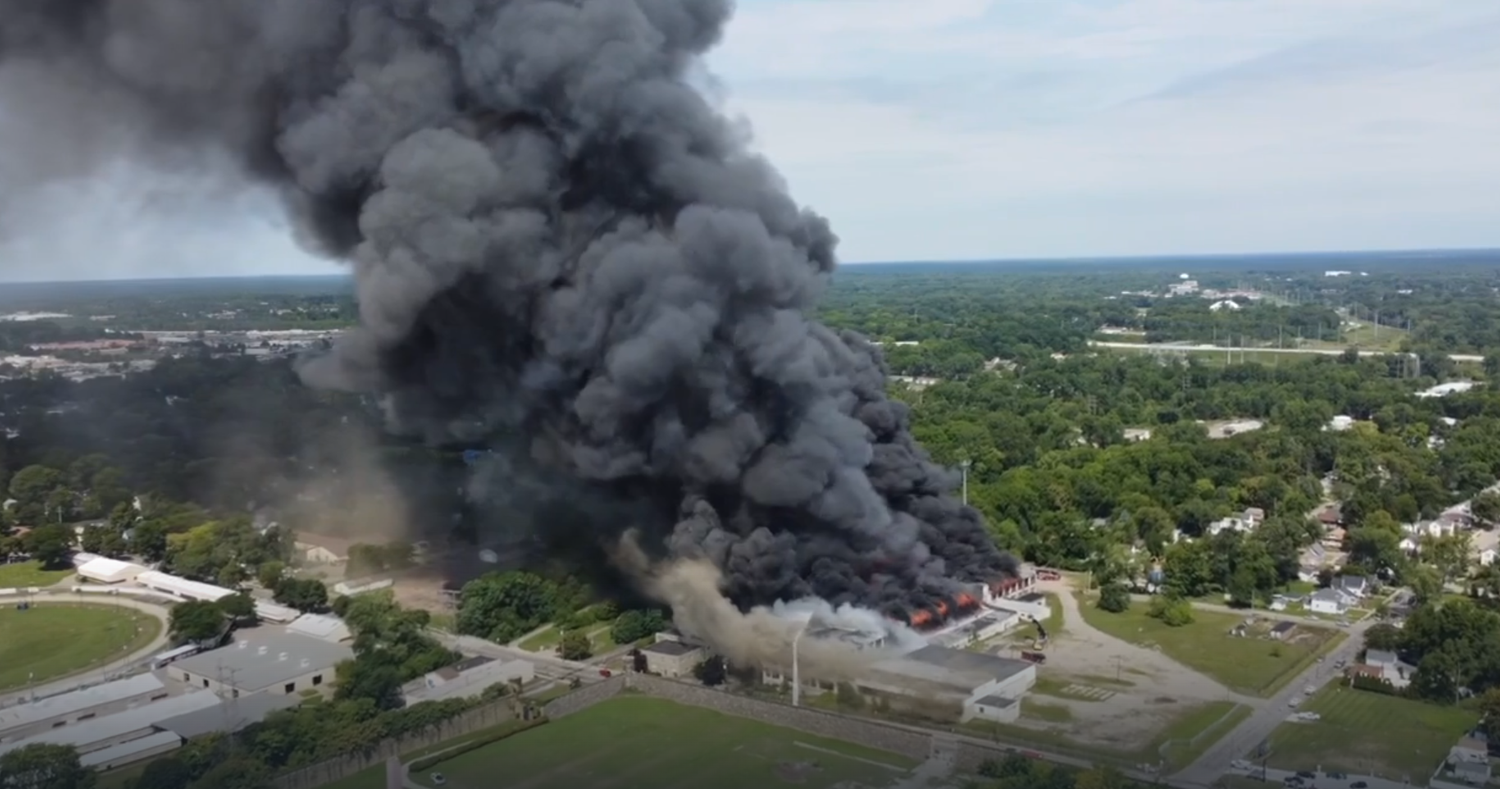
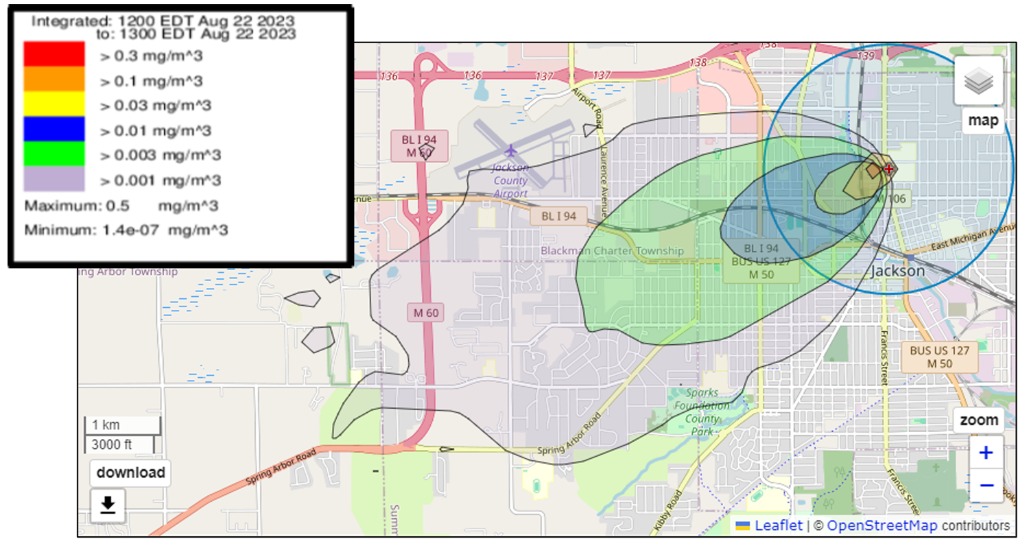
Prototype of the Integrated U.S. Greenhouse Gas Measurement, Monitoring, and Information System (GHGMMIS)

NOAA’s Air Resources Laboratory (ARL) is developing an operational capability to measure and model U.S. emissions of greenhouse gases (GHG). NOAA, in collaboration with the National Institute for Standards and Technology (NIST) are developing and testing a prototype system to monitor and measure GHG emissions on local, regional, and national scales. Initially, this capability integrates existing, mature capabilities into an urban-scale operational GHG monitoring system covering the DC-Baltimore region.

The Greenhouse Gas Measurement, Monitoring, and Information System (GHGMMIS)

The primary goal of the urban-scale prototype GHG Measurement, Monitoring, and Information System is to reduce the latency in the provision of GHG emissions estimates. Current estimates are generally available on an annual basis. Creating such a product on a more frequent basis will enable better collaborations between regional and local city planners and federal agencies to monitor and verify their GHG emissions mitigation plans. The prototype system being developed is based on contemporaneous observations of GHG concentrations in the atmosphere, and as such, can provide an independent check on, and complement, traditional emissions estimating methods.

Monitoring Greenhouse Gas Sources

This GHG Measurement, Monitoring, and Information System constitutes a portion of the US government’s initiative to address greenhouse gas emissions. The initial version of the prototype system being developed will target CO2, as it is the most significant GHG contributing to climate change, and approximately 70% of anthropogenic CO2 emissions are generated in urban areas. The next phase of the system will add methane (CH4), as it is also a large contributor to climate change and has significant urban emissions. This program will foster a better understanding of GHG emissions, which is essential to designing and evaluating efforts to reduce emissions. This system aims to not only improve the accuracy of emissions estimates, but also to provide more frequent insights into the results of efforts to reduce emissions. As GHG emissions mitigation policies are adopted, stakeholders will be able to monitor the results of their efforts.

Put simply, the prototype CO2 system starts with atmospheric measurements of CO2 in the DC-Baltimore region and estimates what the emissions must have been to have created the observed CO2 concentrations. As such, it is classified as a top-down emissions-estimating system, as it starts from observable concentrations of CO2 in the air. The process of using downwind observations to estimate emissions is used in a number of different air pollution applications and is commonly called an inversion. A short description of the inversion methodology follows.

The methodology

CO2 Observations

NIST’s Northeast Corridor greenhouse gas observation network provides fundamental input data to the prototype system. This network of tower-based carbon dioxide and methane observation stations was established in 2015 with the goal of quantifying GHG emissions in urban areas in the northeastern United States. A focus of the network is on Baltimore, MD, and Washington, DC, with a high density of observation stations in these two urban areas. Additional observation stations are available in the northeastern US to provide supplementary data on emissions throughout this complex region with a high population density and multiple metropolitan areas. 

Regional map of NIST Northeast Corridor tower locations. Map at left shows detailed area near Washington, DC, and Baltimore, MD. Green triangles indicate regional sites, red triangles indicate urban sites, and blue triangles are rural or background sites surrounding the Washington–Baltimore region. Image Credit: NIST
The DC skyline at sunrise, as seen from Arlington National Cemetery. The Eternal Flame at Pres. Kennedy’s gravesite is at the bottom of image. Image credit: U.S. Army photo by Rachel Larue/Arlington National Cemetery/released.

Meteorological Modeling

A high-resolution meteorological modeling simulation will be conducted over the region, assimilating a wide variety of meteorological measurements. This simulation is a “reanalysis” — rather than a forecast — in that it is carried out after the fact, and takes advantage of meteorological measurements during the period of the simulation to create the best possible characterization of the atmosphere for that time period. This high-resolution meteorological simulation will be used to drive the transport and dispersion model and other system components, as described below.

HYSPLIT Footprints

The NOAA HYSPLIT atmospheric transport and dispersion model will be used to create a series of “footprints,” to estimate the sensitivity of measured CO2 concentrations to upwind surface fluxes. The footprint fields generated by HYSPLIT are one of the key inputs that are passed into the inversion model to estimate CO2 emissions.

Biogenic Emissions

Photosynthesis and other biogenic processes affect CO2 concentrations in the atmosphere, and these must be accounted for in order to estimate anthropogenic emissions. The measurements of CO2 in the region used for the emissions estimates reflect both anthropogenic and biogenic influences. In the prototype system, the Vegetation Photosynthesis and Respiration Model (VPRM) will be used to estimate biogenic sources and sinks within the modeling domain so that they can be accounted for in estimates of CO2  emissions.

Background Concentrations / Boundary Fluxes

COwill enter into the modeling domain, influenced by upwind sources and sinks, and these “boundary fluxes” must be accounted for in order to estimate the emissions within the urban area. The boundary fluxes create a background concentration that must be subtracted from the CO2 measurements in the urban area to isolate the emissions in the urban area. The prototype system will utilize CO2 measurements at upwind stations to estimate these background fluxes.

HYSPLIT generated footprints driven by the HRRR NWP model output for the NIST tower located in Arlington, VA, covering measurements taken during the afternoon hours (12-4pm EST) in January 2019. Higher footprint values reveal regions that are more susceptible to surface fluxes that impact the measurements at this location and time window. HYSPLIT simulations suggest that for the afternoon hours of January 2019, Arlington, VA is more sensitive to CO2 fluxes from the south-southwest and northwest. The diamonds show the locations of all NIST towers.

Anthropogenic Emissions Priors

The prototype system starts with a first guess (or “prior” estimate) of the emissions in the region, and then uses the CO2 measurements to estimate how these emissions should be adjusted so that they better match the CO2 measurements. The first guess emissions used in the prototype system will be based on the GRA2PES emissions inventory system developed by NOAA’s Chemical Sciences Laboratory (CSL) in collaboration with NIST. 

Inversion using CarbonTracker-Lagrange

Once the above system components are assembled for a given month, they will be used as inputs to an inversion model – the CarbonTracker-Lagrange (CT-L) model developed by NOAA’s Global Monitoring Laboratory (GML). Conceptually, CT-L uses the time series of measured atmospheric concentrations of CO2 attributed to anthropogenic sources in the DC Baltimore region (i.e., the signals with both the background and biogenic influences removed as described above) to estimate how much CO2 would have had to be emitted upwind of the measurement sites to produce the observed signals. The HYSPLIT footprints driven with the meteorological model fields provide the linkage between the emissions and observed concentrations that is required by the inversion technique. 

Uncertainties

A fundamental component of the prototype being developed will be estimates of uncertainties in the emissions estimates being generated. Stakeholders need to be aware of these uncertainties in order to better interpret the results of the system. Analysis of uncertainties in each of the system elements, and the entire system, will be continuously carried out in the operational system and included in the results provided by the system. Further, the system’s estimates will also be evaluated by comparison against mobile- and aircraft-based measurements that are periodically carried out in the region. To this end, NOAA carries out mobile GHG measurements with a specially outfitted vehicle throughout the DC-Baltimore region. Further, flight-based GHG measurement campaigns are carried out in the region in collaborations between NOAA, NIST, and other institutions.

Post-processing, Publishing, and Distribution of Results

The prototype GHG Measurement, Monitoring, and Information System being developed is currently configured to generate monthly emissions estimates, and it is anticipated that estimates for a given month will be available within two months. In addition to overall regional emission estimates for a given month, spatially and temporally resolved estimates for each month will also be provided for the region. It is understood that uncertainties will generally increase with estimates made on smaller and smaller temporal or spatial scales. The resolution provided by the system will be determined based on a consideration of stakeholder needs as well as an analysis of relative uncertainties. Once the estimates are complete for a given month, they will be provided on a public-facing website, including graphical, tabular, and other summaries of the results, including trends. More detailed data products will also be available for download. The goal is to make the outputs as useful and relevant to stakeholders as possible. Focus groups and other mechanisms will be used during the development of the system — and after the system becomes operational — to ensure that this goal is met.

Overall map of the system, showing CO2 and meteorological measurement sites, the domain of the high-resolution meteorological modeling domain, and the CarbonTracker-Lagrange domain. The DC and Baltimore beltways, and the portion of I-95 between the two cities, are shown (yellow roads) as they are typical routes for mobile GHG measurements. Image Credit: NOAA Air Resources Laboratory.
Overall system map including gridded CO2 emissions from the GRA2PES emissions inventory for Jan 2019 (mol CO2 km-2 hr-1), within the CarbonTracker-Lagrange modeling domain encompassing the Washington DC - Baltimore urban region. Image Credit: NOAA Air Resources Lab.